
Non-contact Labyrinth Seal
LYF Series Stainless Steel Non-contact Labyrinth Seal
High-speed shaft protection from dust, chips, oil mist and liquid splash
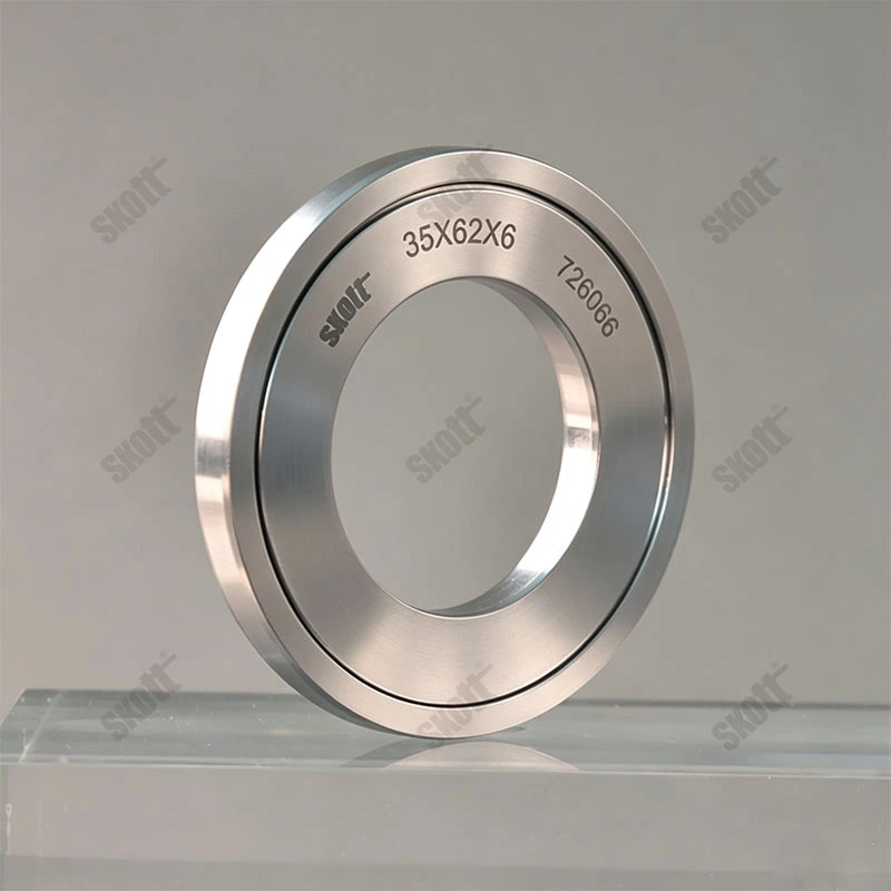
Multi-stage axial/radial non-contact labyrinth construction for high-speed shaft and bearing-end protection.
- Model
- LYF Series
- Material
- Stainless steel
- Temperature
- -200 to 300 C (confirm with assembly and operating conditions)
- Pressure Capability
- Non-pressure design; use a combined sealing arrangement where pressure differential, gas tightness or liquid-leakage control is required
- Speed
- Theoretically unlimited
- Primary Contaminants
- Dust, chips, oil mist, coolant and washdown-water splash
- Operating Method
- Inner and outer rings do not contact in normal operation; control concentricity, shaft runout, radial clearance and axial location
- Standard Dimensions
- Standard shaft diameters 10–100 mm and standard width 6 mm; custom sizes available
Operating Principle and Core Benefits
The LYF stainless steel non-contact labyrinth seal protects high-speed shaft and bearing ends. Multi-stage axial and radial labyrinth passages redirect, throttle, return and expel external dust, chips, oil mist and coolant before they reach the bearing area. The inner and outer rings do not contact each other in normal operation. LYF is a non-pressure protective design; where continuous liquid level, pressure differential, gas tightness or liquid-leakage control is required, combine it with a contact seal such as a PTFE stainless steel oil seal.
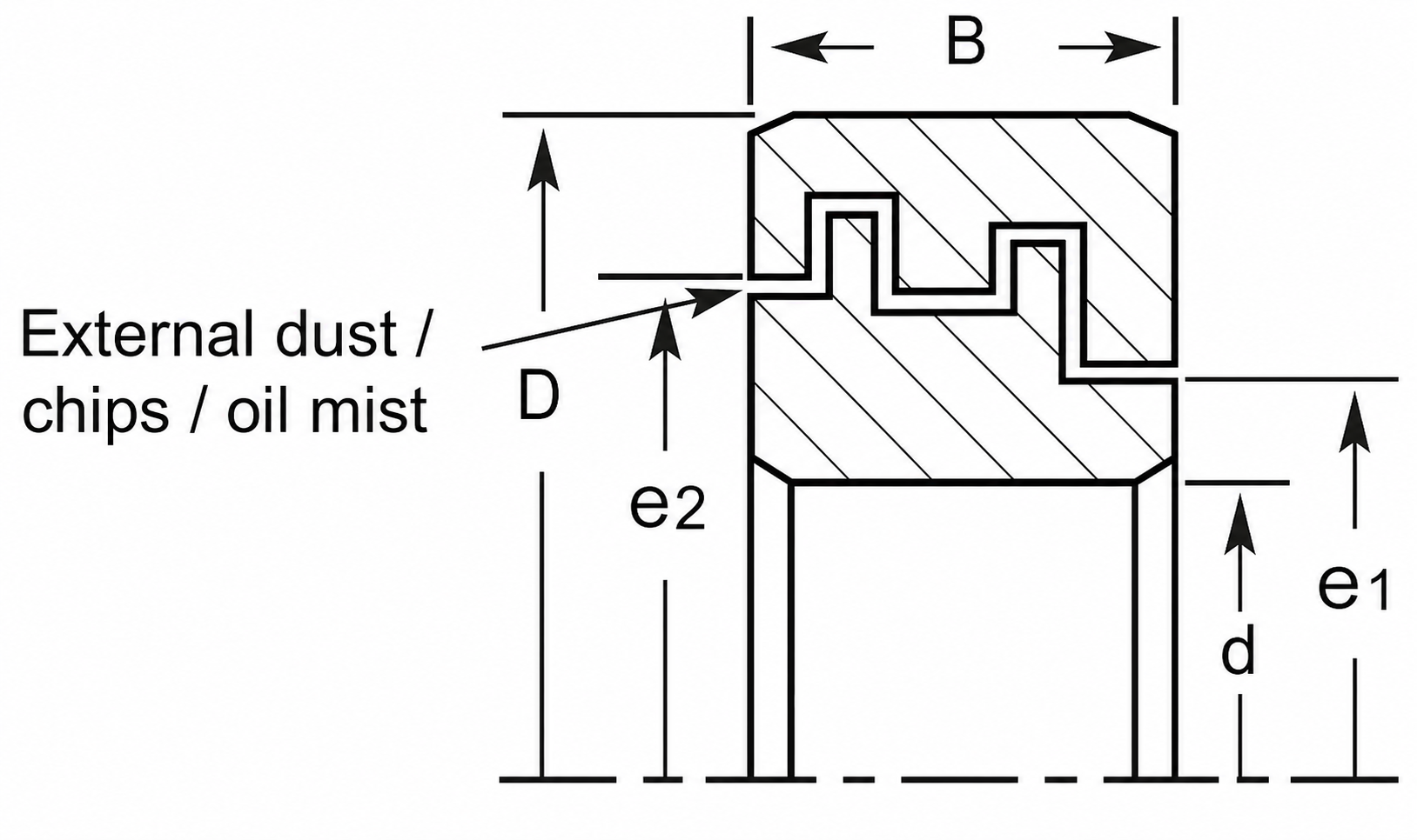
Standard Model Dimensions
The following are standard model dimensions. Actual allowable speed must be confirmed against shaft diameter, surface speed, interference fit, dynamic balance, shaft runout and operating temperature.
View All Standard Dimensions
| Model | Shaft d mm |
OD D mm |
Width B mm |
e1 mm |
e2 mm |
Weight kg |
Part No. |
|---|---|---|---|---|---|---|---|
| LYF6200 A0 | 10 | 30 | 6 | 17 | 27 | 0,010 | F65851 |
| LYF6201 A0 | 12 | 32 | 6 | 19 | 29 | 0,011 | F67371 |
| LYF6202 A0 | 15 | 35 | 6 | 22 | 32 | 0,013 | F60801 |
| LYF6203 A0 | 17 | 40 | 6 | 25 | 35 | 0,017 | F62551 |
| LYF6004 S10 | 20 | 42 | 6 | 28 | 38 | 0,051 | F759711 |
| LYF6204 A0 | 20 | 47 | 6 | 29 | 39 | 0,023 | F75921 |
| LYF6005 S10 | 25 | 47 | 6 | 33 | 43 | 0,059 | F709211 |
| LYF6205 A0 | 25 | 52 | 6 | 34 | 44 | 0,026 | F70271 |
| LYF6006 S10 | 30 | 55 | 6 | 39 | 49 | 0,079 | F850011 |
| LYF6206 A0 | 30 | 62 | 6 | 42 | 52 | 0,037 | F85171 |
| LYF6007 S10 | 35 | 62 | 6 | 45 | 55 | 0,097 | F801711 |
| LYF6207 A0 | 35 | 72 | 6 | 48 | 58 | 0,050 | F80271 |
| LYF6008 S10 | 40 | 68 | 6 | 50 | 60 | 0,113 | F951311 |
| LYF61908 S10 | 40 | 62 | 6 | 48 | 58 | 0,084 | F951711 |
| LYF6208 A0 | 40 | 80 | 6 | 54 | 64 | 0,061 | F95351 |
| LYF6009 S10 | 45 | 75 | 6 | 55 | 65 | 0,134 | F902011 |
| LYF61909 S10 | 45 | 68 | 6 | 53 | 63 | 0,097 | F001311 |
| LYF6209 A0 | 45 | 85 | 6 | 58 | 68 | 0,066 | F00301 |
| LYF6010 S10 | 50 | 80 | 6 | 60 | 70 | 0,145 | F053511 |
| LYF61910 S10 | 50 | 72 | 6 | 58 | 68 | 0,100 | F052711 |
| LYF6210 A0 | 50 | 90 | 6 | 63 | 73 | 0,071 | F05451 |
| LYF6011 S10 | 55 | 90 | 6 | 67 | 77 | 0,189 | F004511 |
| LYF61911 S10 | 55 | 80 | 6 | 63 | 73 | 0,126 | F003511 |
| LYF6012 S10 | 60 | 95 | 6 | 72 | 82 | 0,202 | F154011 |
| LYF61912 S10 | 60 | 85 | 6 | 68 | 78 | 0,135 | F153011 |
| LYF6013 S10 | 65 | 100 | 6 | 77 | 87 | 0,215 | F1065511 |
| LYF61913 S10 | 65 | 90 | 6 | 73 | 83 | 0,144 | F104511 |
| LYF6014 S10 | 70 | 110 | 6 | 83 | 93 | 0,268 | F256651 |
| LYF61914 S10 | 70 | 100 | 6 | 80 | 90 | 0,190 | F256551 |
| LYF6015 S10 | 75 | 115 | 6 | 89 | 99 | 0,283 | F2066011 |
| LYF61915 S10 | 75 | 105 | 6 | 85 | 95 | 0,201 | F205651 |
| LYF6016 S10 | 80 | 125 | 6 | 94 | 104 | 0,343 | F3567011 |
| LYF61916 S10 | 80 | 110 | 6 | 90 | 100 | 0,212 | F356651 |
| LYF6017 S10 | 85 | 130 | 6 | 100 | 110 | 0,360 | F3068511 |
| LYF6018 S10 | 90 | 140 | 6 | 107 | 117 | 0,428 | F4569511 |
| LYF6019 S10 | 95 | 145 | 6 | 112 | 122 | 0,447 | F6069011 |
| LYF6020 S10 | 100 | 150 | 6 | 117 | 127 | 0,465 | F65569511 |
Selection and Installation Checklist
- Confirm shaft diameter and housing bore.
- Confirm available axial width.
- Provide rotational speed or surface speed.
- Confirm minimum and maximum operating temperatures.
- Identify whether the contaminant is dust, oil mist or liquid splash.
- Confirm splash direction and whether continuous liquid level or pressure is present.
- Check shaft runout, concentricity and allowable radial clearance.
- Confirm inner-ring interference fit and axial retention.
- Arrange drainage and return paths for the installation orientation.
- Determine whether a PTFE stainless steel oil seal is required in combination.
Equipment Applications and Operating Limits
High-speed Machining Spindles
Blocks cutting fluid, metal chips and oil mist from entering spindle-bearing areas where low-friction shaft-end protection is required.
High-speed Motors and Fans
Protects bearing ends in environments containing dust, particles and external oil mist without adding contact-lip friction.
Pumps and Compressors
Isolates external splash, oil mist and environmental contaminants. Where chamber pressure or liquid-leakage control is required, combine it with a PTFE contact seal.
Compressors and Refrigeration Equipment · Fluid and Process Equipment
Related Products:PTFE Stainless Steel Oil Seals
Downloads
LYF Stainless Steel Non-contact Labyrinth Seal Specification
Includes operating principle, technical data, standard dimensions, installation requirements, speed-confirmation criteria and application limits for offline selection and procurement review.
Frequently Asked Questions
Can an LYF labyrinth seal fully replace an oil seal?
Not in every application. LYF provides low-friction protection against external contamination. Where pressure differential, gas tightness, continuous liquid level or liquid-leakage control is required, combine it with a contact seal such as a PTFE stainless steel oil seal.
Can it be used under continuous immersion?
LYF is suitable for intermittent splash and external-contaminant exclusion, but is not recommended as the sole seal for continuous immersion. Continuous liquid-level applications require evaluation of drainage direction and pressure differential together with a contact seal.
How is maximum speed determined?
Calculate surface speed from shaft diameter and rotational speed, then confirm inner-ring interference, axial retention, dynamic balance, shaft runout and temperature. Ceimin engineering review is recommended above 60 m/s.
Which dimensions must be controlled during installation?
Control shaft diameter, housing bore, interference fit, concentricity, shaft runout, radial clearance, axial location and available width. The labyrinth and drainage orientation must match the contamination source.
Can it achieve IP65 or IP67?
An IP rating is a complete-enclosure test result and cannot be claimed from one labyrinth seal alone. Confirm it through the installation design, running clearances, spray direction and complete-equipment testing.
How long does a non-contact labyrinth seal last?
The non-contact design has no continuous conventional lip wear, but service life still depends on corrosion, assembly error, vibration, contaminant buildup, temperature and rotor condition. Inspect it according to the equipment maintenance schedule.
Request a Quote
Provide shaft diameter, housing bore, available width, speed, temperature, contaminants, splash direction, pressure, shaft runout and retention method so that a standard model or custom design can be confirmed.